OPTIMUM COMPACTION WET & DRY - civil engineering vk

OPTIMUM COMPACTION WET & DRY - civil engineering vk

Optimum Compaction Wet and dry 

Dry of Optimum Compaction and Wet of Optimum compaction

Comparing between and dry and wet of optimum compaction

    Properties
changes with compaction
Dry optimum Wet of Optimum
 Structure
after compaction
 Flocculated
(Random)
 Dispersed
(Oriented)
Water deficiency More   Less
Permeability More,
 Isotropic
 Less,
 Isotropic
Compressibility   
at low stress Low  Higher
at high stress High   Lower
Swelleability High  Low
Shrinkage Low  High
Stress strain Behavior Brittle,high peak,
Higher elastic modulus
 Ductile, No peak,
Lower elastic modulus.
Strength (undrained)
as mould after saturation
 High Much lower
Construction Pore Water 
Pressure
Low High
Sensitivity of the Soil related to shear strength in Laboratory test - Civil Engineering Study VK

Sensitivity of the Soil related to shear strength in Laboratory test - Civil Engineering Study VK

SENSITIVITY OF SOIL - Soil Mechanics

Sensitivity elated to shear strength of soil in Laboratory test

  •     It is defined as the ratio of undisturbed strength to that of the remoulded strength
  •     Sensitivity = Undisturbed Strength / Remoulded Strength

Sensitivity of Soil

 Sensitivity Nature of Soil
 1 Insensitive
 1 to 4 Normal
 4 to 8 Sensitive
 8 to 16  Extra -Sensitive
 >16 Quick
TYPES OF TEST ON BRICKS - IS code 3495 - civil engineering study

TYPES OF TEST ON BRICKS - IS code 3495 - civil engineering study

Types of Tests On Bricks IS code 3495 

Following tests are conducted on bricks to determine its suitability for construction work.

  • Absorption test
  • Crushing strength test
  • Hardness test
  • Shape and size
  • Color test
  • Soundness test
  • Structure of brick
  • Presence of soluble salts (Efflorescence Test)
 

 WATER Absorption Test on Bricks - 3495 PART 2

  • Absorption test is conducted on brick to find out the amount of moisture content absorbed by brick under extreme conditions. 

Apparatus:

  • Oven, 
  • Weight balance, 
  • Tray

PROCEDURE

  • Take any five random bricks from a lot of brick as a specimen.
  • Dry the specimen in a ventilated oven at a temperature of 105°C to 115°C till it achieves considerably constant mass.
  • Cool the specimen to room temperature and take its weight (M1).
Testing:
  • When the specimen is completely dry, then immerse it in the clean water at the room temperature (27 ±2°C) for 24 hours.
  • Remove the specimen from the water after 24 hours and wipe out water with a damp cloth and weigh the specimen.
  • Take the weight (M2) of the specimen after 3 minutes of removing from the water.
  • Points to be Taken Care:
  • When you take M1, If the Specimen is warm while touching, it shall not be used for the test. Test it when you feel it cool.

Result:

  • Note down the M1 and M2.
  • Percentage of Water absorption of brick by its mass, after 24-hour immersion in cold water is calculated by the following formula
  • (M2-M1)/M1*100

  • For a good quality brick the amount of water absorption should not exceed 20% of weight of dry brick.
TYPE                         WATER ABSORBTION
FIRST CLASS         < 20%     OR 15% AVERAGE
SECOND CLASS     < 22.5%  OR 20% AVERAGE
THIRD CLASS         < 25%      OR 25% AVERAGE
 

Crushing Strength or Compressive Strength Test on Bricks - IS 3495 PART 1

  • Place the specimen with flat face s horizontal and mortar filled face facing upwards between plates of the testing machine.
  • Apply load axially at a uniform rate of 14 N/mm2 (140 kg/cm2) per minute till failure occurs and note maximum load at failure.
  • The load at failure is maximum load at which the specimen fails to produce any further increase in the indicator reading on the testing machine.
  •  Compressive Strength of Bricks = Maximum Load at Failure (N)/Average area of bed face (mm2)
  • The average of result shall be reported.
  • Crushing strength of bricks is determined by placing brick in compression testing machine. 
  • After placing the brick in compression testing machine, apply load on it until brick breaks. 
  • Note down the value of failure load and find out the crushing strength value of brick. 
compressive strength
in N/mm2
    >10.5
    first class    
    7.5
 second class 
    5.5
 third class 
 
compressive strength of common bricks should not be used if it is  less than 3.5N/mm2
 
 
Bricks Class Designation Average compressive strength of Bricks
Not less than (N/mm2) Less than (N/mm2)
350 35 40
300 30 35
250 25 30
200 20 25
175 17.5 20
150 15 17.5
125 12.5 15
100 10 12.5
75 7.5 10
50 5 7.5
35 3.5 5
 

Efflorescence Test on Bricks - IS 3495 PART - 3

  • A good quality brick should not contain any soluble salts in it. 
  • If soluble salts are there, then it will cause efflorescence on brick surfaces.
Type area affected
Nill EffloresenceVery Low
Slight0-10%
Moderate10-50%
Heavy>50%
Serious
>50% + deposit are 
present in powder forms
Heavy Flakes
 

WARPAGE TEST - IS 3495 PART 4

  • check the bricks for warpage of brick like concave and convex warpage with the help of glass or stell surface
 

Hardness Test on Bricks

  • A good brick should resist scratches against sharp things. 
  • So, for this test a sharp tool or finger nail is used to make scratch on brick.
  •  If there is no scratch impression on brick then it is said to be hard brick.
for any doubt finger nail means


Shape and Size Test on Bricks (dimension test) - IS 1077

  • Shape and size of bricks are very important consideration. All bricks used for construction should be of same size. The shape of bricks should be purely rectangular with sharp edges.
  • Standard brick size consists length x breadth x height as 19cm x 9cm x 9cm.
  • To perform this test, select 20 bricks randomly from brick group and stack them along its length , breadth and height and compare. 
  • So, if all bricks similar size then they are qualified for construction work.
 
Dimension
Test

Dimension
should not greater than below value

Length -19×20= 380 ± 12 cm
Breadth - 9×20 = 180 ± 6 cm
Height - 9×20 = 180 ± 6 cm

here 20 indicate 20 no of bricks
used in sample


Color Test of Bricks

  • A good brick should possess bright and uniform RED color throughout its body.
 

Soundness Test of Bricks

  • Soundness test of bricks shows the nature of bricks against sudden impact.
  • In this test, 2 bricks are chosen randomly and struck with one another. 
  • Then sound produced should be clear bell ringing sound and brick should not break. 
  • Then it is said to be good brick.Soundness Test of Bricks
 

Structure of Bricks

  • To know the structure of brick, pick one brick randomly from the group and break it. 
  • Observe the inner portion of brick clearly. It should be free from lumps and homogeneous.Structure of Bricks
 
What are the properties of high density concrete in dry state?

What are the properties of high density concrete in dry state?

What are the properties of high density concrete in dry state?


High density Concrete

  • 1. High density concrete is those concrete which have best packaging with the presence of finest to coarse particles of substance of concrete which gives best denseness of concrete.
  • 2. It is achieved by using the knowledge of concrete with skills.
  • 3. It is achieved by using of some admixtures or additionally use of special ingredients of concrete

  • 4. For making high density concrete first step is choosing the right materials for it.
  • 5. It requires heavier aggregates with specific gravity of 3.5 to 4.which give
  • 6. Some Natural aggregates used in High dense concrete is Limonite, Haematite, Magnetite,Barite etc.

  • 7. like finest grade of cement.small to higher proportion of fine to coarse aggregate which gives better packaging of concrete and most important part is using of water reducing agent which removes extra part of water some plasticize,skilled labor who knows how to mix it.
  • 8.for mixing or preparation first coarsest aggregate is spread on floor then finer particles are spread over it in order of their degree and after that mix thoroughly till homogenous mix obtain after that water and plasticizer are used.
  • 9. now we ready for making high density concrete 
  • 10. for next steps we want some form-work and compaction instruments which imparts the density of concrete. during these process some precautions are taken like taking the precaution for not having segregation, bleeding, too much water, honey combing, too much time taken for preparing and using of green concrete etc.


How to know what is high density concrete

  • For knowing what is high density concrete and where is it use and how it works we must know all about the Properties of high dense Concrete.

Properties of high density Concrete

1. It is highly durable.

2. It Have highest toughness. 

3. It is impermeable.

4.Sulfate resisting properties, 

5. It is heavier than other concrete work

6. It have very high mechanical properties as strength and durability.
  • Strength of concrete at 28 days - greater than 40MPa
  • coefficient of thermal expansion is almost twice than normal concrete
  • shrinkage is about 1/4 to 1/3rd of normal concrete

7. High Shielding properties from all radiations and other mechanical forces.

8. It reduces the intensity of neutrons, gama and other rays by absorbing its particles and gives shield against radiation on nuclear projects. and shield are electronic instruments from high temperature and radiations.

9. Ease of Constructions due to its process of manufacturing.

10. weight of High density concrete is very high in the range of 3360 to 3900 kg/m3

11. It is Highly Dense - 
  • Higher the density of concrete higher the absorption of radiation
12. Absense of air voids


For more you should read on following link page


CIVIL ENGINEERING SUBJECTS

CIVIL ENGINEERING SUBJECTS

CIVIL ENGINEERING SUBJECTS

LIST OF ALL SUBJECTS RELATED TO CIVIL ENGINEERING STUDY

We provide list of all the civil engineering subjects which is essentials and without it no one never be a civil engineering.... Students who study or will study in college still reads these following subject.

  • Engineering Mechanics
  • Environmental Engineering
  • Soil Mechanics
  • Concrete Technology
  • Reinforced concrete construction (RCC)
  • Strength of Material (SOM)
  • Structural Steel Engineering
  • Structure Analysis
  • Solid Waste Management
  • Structural Engineering Design
  • Fluid Mechanics
  • Irrigation Engineering
  • Surveying or Survey Engineering
  • Engineering Mathematics 
  • Geo-technical Engineering
  • Applied Physics
  • Engineering Chemistry
  • Elements of Electrical Engineering
  • Engineering Drawing and Planing

  • Building Materials
  • Building Construction
  • Foundation Engineering
  • Construction Management
  • Waste Water Management
all the above subjects and its syllabus which is most important related to civil engineering exams and practices are discussed later with another posts

Irrigation and Its Methods in Civil Engineering Study

Irrigation and Its Methods in Civil Engineering Study

Irrigation and Its Methods for Engineering Purpose

Irrigation


CHAPTER HIGHLIGHTS

☞ Introduction
☞ Types of irrigation
☞ Methods of irrigation
☞ Water requirements of crops
☞ Irrigation efficiencies
☞ Irrigation requirements of crops
☞ Crop seasons
☞ Water logging and drainage


GENERAL UNDERSTANDING

The following are the main concerns on irrigation:-

1 How to apply

  • i.e. what should be the method of irrigation: Border Flooding method, furrow irrigation method,sprinkler irrigation method, drip irrigation method etc.

2.How much apply

  • i.e. how much moisture the soil can hold in its pores or Moisture holding capacity of Soil.

3.When to apply

  • i.e. when has the soil moisture level depleted to 50 to 60% of moisture holding capacity and when is the time to irrigate. In other words, what should be the frequency of irrigation.


DEFINITION OF IRRIGATION

Irrigation may be defined as the science of artificial application of water to the land, in accordance with the crop requirements throughout the crop period for full-fledged nourishment of the crops.


CROP YIELD AND PRODUCTION IN IRRIGATION

The crop yield from irrigation is expressed as quintal/ha or tonnes/ha. The productivity of the crop is expressed as crop yield per mm of water applied.

Increase of yield or Productivity can be achieved by following methods in IRRIGATION

  • Land shaping or land leveling
  • Suitable crop rotation and crop planing
  • Using high yielding varieties of seeds
  • Using chemicals and Fertilizers
  • Suitable methods of Irrigation adopted.
  • Lining of canal and other bodies.
  • Drainage of Irrigated land by surface and subsurface drainage.

ADVANTAGES AND DISADVANTAGES OF IRRIGATION

Advantages of Irrigation

Direct advantages of IRRIGATION

  • Increase in food Production
  • Protection against drought
  • Revenue generation
  • Mixed Cropping

Indirect advantages of IRRIGATION

  • Power generation
  • Transportation
  • Ground water table
  • Employment

Disadvantage of Irrigation

  • Water logging due to excess irrigation
  • Ground water pollution due to seepage of nitrates resent in soil as fertilizer etc.

Overall Benefits of Irrigation

  • 1. Increase in food production
  • 2. Protection from famine
  • 3. Cultivation of cash crops
  • 4. Eliminating mixed cropping
  • 5. Addition to the wealth of the country
  • 6. Generation of hydroelectric power
  • 7. Domestic and industrial water supply
  • 8. Inland navigation
  • 9. Canal planting
  • 10. Improvement of ground water storage

Effects of Irrigation

  • 1. Breeding places of mosquitoes
  • 2. Water logging
  • 3. Damp climate

TYPES OF IRRIGATION PROJECTS


Irrigation projectsIrrigation Potential (CCA)Cost of Project
Major>10000 ha>5 crores
Medium2000 - 10000 ha>.5 to 5 crores
Smallless than 2000 ha>.25 to .5 crores

TYPES OF IRRIGATION


Types of Irrigation

Flow Irrigation

Lift Irrigation

Perennial IrriagationDirect IrrigationInundation IrrigationStorage IrrigationCombined Storage and Diversion scheme(well irrigation)
(The water required is supplied to the crop through out the year) (diversion scheme) (or) (River canal irrigation) (Water is directly diverted to canal without storing) (The irrigation is carried out by deep flooding) (storage scheme) (or) (Tank irrigation) (Water is stored in dam (or) reservoir) (Water is stored in dam (or) reservoir and then diverted to canal) (Subsoil water is lifted to the Surface and conveyed to agricultural fields.)


  • 1. Surface irrigation.
  • 2. Subsurface irrigation.

Surface irrigation

Surface irrigation can be further classified into 
a. Flow irrigation.- i.e. flow under the action of gravity
b. Lift irrigation.- i.e. water is lifted by pumps etc for supplying water.

Flow irrigation can be further sub-divide into
x. Perennial irrigation - water is supplied on whole base period or continuous required water supply.
y. Flood irrigation - uncontrolled irrigation or soil is kept submerged and thoroughly flooded with water.

Sub-surface irrigation

Sub-surface irrigation may be divided into two types.
a. Natural sub-irrigation - water leakage from channels etc.
b. Artificial sub-irrigation - by artificial mechanism.


METHODS OF IRRIGATION

  • Free flooding method
  • Border flooding method
  • Check flooding method
  • Basin flooding method
  • Furrow irrigation method
  • Sprinkler irrigation method
  • Drip irrigation method

Free flooding or Ordinary flooding

  • Also called wild flooding as the movement of water is not restricted.
  • Initial cost of land preparation is low but labour requirement are usually high.
  • Water application efficiency is also low
  • Suitable for close growing crops, pastures, etc. particularly where land is steep.
  • It may be used on rolling land or topography irregular where borders, checks, basins,furrows are not feasible.

Border flooding

  • Land is divided into no of strips, separated by low levees called borders.
  • Each strip is of 10 to 20 metres in width and 100 to 400 m in length.
  • Water flows slowly toward the lower end and it infiltrates into the soil as it advances.
  • When water reaches the lower end of the strip the supply is turned off.
  • Size of supply ditch depends upon the infiltration rate of the soil and width of border strip.
  • This method is most popular.

Check Flooding

  • Similar to ordinary flooding except water is controlled by surrounding checked area with levees.
  • Close growing crops such as jowar or paddy are preferred.
  • Deep homogeneous loam or clay soils with medium infiltration rates are preferred
  • Suitable for both more permeable and less permeable soils 
  • less time required for highly permeable soil and vice-versa.

Basin flooding

  • Special type of check flooding and adopted specially for orchard trees.
  • One or more trees are generally placed in the basin and surface is flooded.
  • Shape of basin can be square, rectangular, circular or it may be irregular.
  • Flatter the land surface, easier it is to construct the basin
  • Coarse sands are not suitable for basin irrigation Because of high percolation losses.
  • Size and shape of basins are mainly determined by the land slope. the soil type, the available stream, the required depth of irrigation water to the applied.

Furrow Irrigation or Furrow method

  • Water is applied to the land to be irrigated by series of furrows
  • Furrows are small, parallel channels, made to carry water for irrigating the crops.
  • Infiltrated water spreads laterally between furrows.
  • The crops are usually grown on the ridges between the furrow.
  • One half to one fifth area of land is wetted.
  • Suitable for wide range of soil types, crops and land slopes.
  • Preferred on uniformly flat or gentle slopes which should not exceed .5%.
  • furrows can also be similar to long narrow basin.
  • labor requirement and land preparation is reduced as compare to flooding.

Sprinkler irrigation method

  • In the form of spray over crop through pipe system.
  • Known as overhead irrigation.
  • Used for all types of crops except rice and jute.
  • Used for all types of soils except very heavy soils with low infiltration rates.
  • Beset suited for very light soils as deep percolation losses are avoided.
  • This suit undulating topography and hence land leveling is not necessary.
  • This methods is used mainly by cultivation of tea coffee and vegetables in out country.
Notes :- 
  • for rice and jute standing water is required
  • light soils are sandy and silty with very little clay. generally easy to work, warm up quickly, dry out rapidly.

Drip irrigation method

  • Latest method.
  • Popular in areas with acute scarcity of irrigation water and salt problems.
  • Water and fertilizer is slowly and directly applied to the root zone of the plants in order to reduce losses due to evaporation and percolation.
  • Also known as Trickle irrigation
  • Help of specially designed emitter and drippers.
  • Centrifugal pump is best suited for this method.
  • Best suited for row crops such as tomatoes, grapes,corn,citrus,melons,fruits,cauliflower,cabbage etc.

Water Requirements of Crops

  • The water holding capacity of soil is the main characteristics which has to be taken into account for ideal irrigation. Thus the following topics deal with the water holding characteristics of soil and the parameters which help to measure it.

Classes of Soil Water

1. Saturation capacity:

  • The amount of water required to fill the pore spaces between soil particles by replacing all air held in pore spaces. It is also called maximum moisture holding capacity or total capacity.

2. Field capacity:

  • It is the moisture content of soil after free drainage has removed most of gravity water. It is the upper limit of water content available to plant roots.

3. Permanent wilting point:

  • Plants can no longer extract sufficient water from the soil for its growth.This is also known as wilting coefficient. If the plant does not get sufficient water to meet its needs,it will wilt permanently. For most of the soils wilting coefficient is about 150% of hygroscopic water.

4. Temporary wilting:

  • This will take place on a hot windy day but plant will recover in cooler day.

5. Ultimate wilting:

  • At ultimate wilting point the plant will not regain its turgidity even after addition of sufficient water to the soil and the plant will die. It is similar to hygroscopic coefficient.
  • Hygroscopic coefficient = 2/3(permanent wilting point)

6. Available moisture:

  • Moisture content of soil between field capacity and permanent wilting point.

7. Readily available moisture:

  • 75% of available moisture is known as readily available moisture. Readily available moisture depth, d w = S × d (Field capacity – Optimum moisture) = Sd (FC – OM)

8. Moisture equivalent

  • = Field capacity = (1.8 to 2) × (Permanent wilting point) = 2.7 (Hygroscopic coefficient)

9. Available moisture depth

  • = (d w ) = Sg × d × [F C – w C]
  • Where
    S g = Apparent specific gravity of soil
    F c = Field capacity
    w c = Wilting coefficient.

10. Frequency of irrigation

  • f= dw/Cu
  • Where dw = Readily available moisture depth
  • cu = Evapo-transpiration loss

11. Base period:

  • Total time between first watering done for preparation of land for sowing of crop and last watering done before its harvesting is called base period.

12. Crop period:

  • Total time elapsed between sowing of crop and its harvesting is called crop period.

13. Duty (D):

  • It is the area of land in hectares which can be irrigated for growing any crop if one cumec of water is supplied continuously to the land for entire base period of crop.

14. Delta (∆):

  • Total depth of water over the irrigated land required by a crop grown on it during the entire base period of the crop.
  • Crop Average = Delta (cm)
  • Rice = 120
  • Wheat = 37.5
  • Cotton = 45
  • Tobacco = 60
  • Sugarcane = 90
`Duty  = 8.64 × Base period / Delta`
B = Base period in days
∆ = delta in metres.

15. Consumptive use or evapotranspiration:

  • It is thetotal loss of water due to plants transpiration and evaporation from the land.
  • Lysimeter is used to measure Cu .One cumec day = 8.64 hectare metres, it is a volumetric unit.
  • It is total volume of water supplied@ 1 cumec in a day.


Irrigation Efficiencies

1. Water conveyance efficiency ( η c ):

  • It is the ratio of quantity of water delivered to the field to the quantity of water diverted into the canal system from reservoir.

2. Water application efficiency ( η a ):

  • It is the ratio of quantity of water stored in the root zone of plants to the quantity of water delivered to the fields.

3. Water use efficiency ( η u ):

  • It is the ratio of quantity of water used beneficially including the water required for leaching to the quantity of water delivered.

4. Water storage efficiency [ η s ]:

  • Ratio of quantity of water stored in the root zone during irrigation to the quantity of water needed to bring water content of the soil to field capacity.

Irrigation Requirements of Crops

1. Consumptive irrigation requirements (CIR):

It is the amount of water required to meet the evapotranspiration needs of a crop CIR = Cu − Re

Re = Effective rainfall

2. Net irrigation requirement (NIR):

Amount of irrigation water required to be delivered at the field to meet evapotranspiration and other needs such as leaching NIR = Cu – Re + Le

Where, L e = leaching

3. Field irrigation requirement

`(FIR) = NIR/ ηa`

4. Gross irrigation requirement

`(GIR) = FIR / ηc`


5. Paleo irrigation:

  • It is the watering done prior to sowing of crop.

6. Kor watering:

  • The first watering after the plants have grown few cm high is known as kor watering

7. Outlet factor:

  • Duty of water at canal outlet is known as outlet factor.

8. Gross command area (GCA):

  • Total area which can be irrigated by canal system if unlimited quantity of water is available is known as gross command area.

9. Culturable command area (CCA):

  • The portion of the GCA which is culturable or cultivable.
  • CCA = GCA – Uncultivable area

10. Culturable cultivated area:

  • That portion of CCA which is actually cultivated during a crop season.

11. Capacity factor:

  • Ratio of mean discharge of canal for a certain duration to its maximum discharge capacity.

12. Time factor:

  • Ratio of number of days the canal has actually run during a watering period to the total number of days of the watering period.

Crop Seasons

1. Kharif crops:

  • These are the crops which are sown in the month of April and harvested in the month of September. Examples: Rice, maize.

2. Rabi crops:

  • These are the crops which are sown in October and harvested in March. (Also called winter crops) Examples: Wheat, tobacco.

3. Perennial crops:

  • These are the crops for which the water is supplied throughout the year. Example: Sugarcane

4. Hot weather crops:

  • These are the crops which are grown between Kharif and Rabi season, i.e., from February to June.

5. Summer crops:

  • The hot weather crops and Kharif crops are combinedly called as summer crops.

6. Dry crops:

  • Crops grown without irrigation and depend only on rainfall for survival.

7. Wet crops:

  • The crops which require irrigation are known as wet crops.


Water Logging and Drainage


Water Logging

  • It is the condition in which there is excessive moisture in the soil making the land less productive.
  • The depth of water table at which it tends to make the land, water logged, depends on the
  • 1. height of capillary fringe and
  • 2. type of crop.


Causes of Water Logging

  • 1. Excessive rainfall in the area
  • 2. Flat ground profile
  • 3. Improper drainage of surface run-off
  • 4. Excessive irrigation


Effects of Water Logging

  • 1. Causes anaerobic conditions near roots of plants.
  • 2. Causes salinity of soil.
  • 3. Causes growth of wild aquatic plants.
  • 4. Lowers the soil temperature which effects the activities of bacteria.
  • 5. It makes cultivation difficult as the water logged areas cannot be easily cultivated.


Water Logging Control

  • 1. By providing efficient under drainage
  • 2. By preventing seepage from reservoirs
  • 3. By introducing crop rotation
  • 4. By improving natural drainage of area
  • 5. By introducing lift irrigation


Drainage

  • It is the means of preventing land from getting water logged as well as to receive the land already water logged.
Self Purification of Stream - Environmental Engineering

Self Purification of Stream - Environmental Engineering

Self Purification of Stream


A polluted stream undergoes self-purification

  • Zone A – Zone of clear water
  • Zone B – Zone of Degradation
  • Zone C – Zone of Active decomposition
  • Zone D – Zone of Recovery
  • Zone E – Zone of recovery

Zone

Main Characteristics

Zone of Clear Water (1 & 5)

Clear water,  presence of fishes.

100% saturation

Zone of Degradation (2)

Dissolved oxygen level falls due to the decomposition of Organic Matter in this Zone.

Dark and turbid water.

Fishes may present

Algae are absent.

40% saturation

Zone of Active Decomposition (3)

Zone of heavy pollution.

Water is very dark and turbid

Dissolved oxygen level falls to Zero.

Critical Oxygen Deficient occurs.

Formation of the dirty scum layer.

Both fishes and algae absents

0% saturation

Zone of recovery (4)

Dissolved oxygen level increases and may reach to saturated value.

Decomposition of organic matter takes place up to the Nitrate level.

Both fishes and Algae reappear.

BOD falls down.

40% saturation


Purification of sewage in river

When sewage or sewage effluents are discharged into the river, river gets polluted temporary, but the conditions do not remain so forever, because the natural forces  of purification such as dilution, sedimentation, oxidation, reduction in sunlight go on acting upon the pollutants  and bring back the water into its original condition. This process known as self purification and various forces responsible for this are described briefly below:

1. Dilution and Dispersion: 

  • When sewage is discharged into large volume of river water, it gets rapidly dispersed and diluted. This results in reduction of concentration of organic matter in sewage.

2. Sedimentation: 

  • The suspended solids in sewage gets settle down into the river bed by the action of gravity.

3. Oxidation: 

  • The organic matter present in sewage gets oxidized by the microorganisms with the help of dissolved oxygen present in river and results in formation of stable products.

4. Reduction: 

  • It occurs due to hydrolysis of organic matter settles down at the bottom of river bed either chemically or biologically.

The above natural forces of purification depend on various factors which are:

  • 1. Temperature
  • 2. Turbulence
  • 3. Velocity of river stream
  • 4. Availability of dissolved oxygen
  • 5. Type and amount of organic matter present
  • 6. Rate of re-aeration.


Important Terms

Hydrolysis:

  • It is a chemical process in which a molecule is cleaved into two parts by the addition of a molecule of water. One fragment of the parent molecule gains a hydrogen ion (H+) from the additional water molecule. The other group collects the remaining hydroxyl group (OH-).

Pyrolysis

  •  It is the process in which the most of organic matter upon heating in an oxygen free atmosphere splits through a combination of thermal cracking and condensation reactions into gaseous, liquid and solid fractions.
  • The process typically occurs at temperatures above 430 °C (800 °F) and under pressure. It simultaneously involves the change of physical phase and chemical composition and is an irreversible process. So it is an endothermic process.

Disposal of refuse - Environmental Engineering

Disposal of refuse - Environmental Engineering

Disposal of refuse and Sewage sickness of Land


Method of disposal of refuse


Landfill or Burying:

  • Landfill refers to the disposal of waste material by burying it.
  • It is an extended storage area for non-biodegradable waste.
  • Landfill is an area, which prevent contamination from the waste entering the area surrounding by soil and water and it also helps to reduce odor and pests

Incineration: 

  • This method involves burning of solid wastes in a furnace until the wastes are turned into ashes
  • In this process, the combustible portion of the waste is combined with oxygen forming carbon dioxide and water, which are released into the atmosphere
  • Incinerators are made in such a way that they do not give off extreme amounts of heat when burning solid wastes
  • Suitable temperature and operating conditions are required to achieve for incineration
  • It reduces the volume of waste up to 20 or 30% of the original volume
  • This method of solid waste management can be done by individuals, municipalities and even institutions
  • It involves of two stages involved such as drying and combustion. Drying and combustion may be accomplished either in separate units or successively in same units depending upon the temperature constraints or control parameter. It is an exothermic process.

Fluidized bed incineration:

  • It is a combustion technology used to burn solid fuels. 
  • In its most basic form, fuel particles are suspended in a hot, bubbling fluidity bed of ash and other particulate materials (sand, limestone etc.) through which jets of air are blown to provide the oxygen required for combustion or gasification. 
  • The resultant fast and intimate mixing of gas and solids promotes rapid heat transfer and chemical reactions within the bed

Pulverization 

  • It refers to the action of crushing and grinding heavier solids into the lighter solids.

Composting 

  • It is a natural biological process, carried out under controlled aerobic conditions (requires oxygen).
  • In this process, various microorganisms, including bacteria and fungi, break down organic matter into simpler substances.
  • The effectiveness of the composting process is dependent upon the environmental conditions present within the composting system i.e. oxygen, temperature, moisture, material disturbance, organic matter and the size and activity of microbial populations.


process of composting


Bangalore method

  • It is an anaerobic method conventionally carried out in pits. 
  • In the Bangalore method of composting, dry waste material of 25 cm thick is spread in a pit and a thick suspension of cow dung in water is sprinkled over for moistening.

Indore method

  • It is an aerobic method. 
  • The Indore method of composting in pits involves filling of alternate layers of similar thickness as in the Bangalore method.
  • However, to ensure aerobic condition the material is turned at specific intervals for which a 60 cm wide strip on the longitudinal side of the pit is kept vacant.

There are mainly two methods (Indore and Bangalore method) adopted in India for the decomposition of Solid wastes generated. 


The main difference between Indore Method and Bangalore Method for decomposition of MSW is given below:


Indore Method

Bangalore Method

Decomposition of MSW by composting is done aerobically.

Decomposition of MSW by composting is done an-aerobically.

Decomposition takes 2 - 3 Months

Decomposition takes 5 - 6 Months

Mixing is ensured either Mechanically or manually

 No mixing is done.


  • In Composting with a combination of proper environmental conditions and adequate time, microorganisms turn raw putrescible organic matter into a stabilized product.
  • Through composting, readily available nutrient and energy sources are transformed into carbon dioxide, water, and a complex form of organic matter compost. 
  • Process management can be optimized for a number of criteria, including the rate of decomposition (to reduce residence time in reactors and thus minimize facility size requirements), pathogen control, and odour management.
  • The key parameters are the available carbon to nitrogen (C: N) ratio, moisture, oxygen, and temperature.
  • Decomposition slows dramatically in mixtures under 40 to 45 percent moisture, which can lead facility operators to prematurely assume compost is stabilized and ready to sell.
  • A minimum moisture content of 50 to 55 percent is usually recommended for high rate composting of MSW.
  • During the active composting phase, additional water usually needs to be added to prevent premature drying and incomplete stabilization. MSW compost mixtures usually start at about 52 percent moisture and dry to about 37 percent moisture prior to final screening and marketing.


C/N ratio is an important factor in composting


  • since bacteria use nitrogen for their cell structure building and carbon for food.
  •  The optimum composting C/N ratio should be in range (30 - 50)
  •  So, If C/N ratio is more, Nitrogen is utilized prior to that of carbon, which results in incomplete digestion of organic matter.

gases produced from a land fill site


  • Sanitary landfill involves dumping the waste in layers and compacting them after each layer, hence tractor can be used very effectively for this purpose.It is simple and economical.

  • But there is continuous evolution of foul gases which may be explosive in nature. The major constituent gases produced from a land fill site are carbon dioxide and methane.

  • It also causes leachate in landfills which pollutes the nearby ground water thereby impacting the ecology of the area.


Sewage sickness of  Land: 

  • When sewage is applied continuously on a piece of land, the soil pores or voids may get filled up and clogged with sewage matter retained in them. This phenomenon of soil getting clogged is known as sewage sickness of the land.
The following preventive measures may be adopted to avoid sewage sickness:

Pre-treatment of sewage   

Sewage should be given some pre-treatment before it is applied on land.

Rotation of crops

It is desirable to grow different types of crops on a piece of land instead of one single crop. Rotation of crops minimizes the chances of sewage sickness.

Drainage of soil

Subsoil drain pipes should be laid in sufficient number to collect the percolated effluent.

Depth of sewage

The depth of sewage on land should be carefully decided by keeping in view the climatic conditions, drainage facilities, nature of crops, and characteristics of the soil.

Alternative arrangement

 There should be ample provision of extra land so that land with sewage sickness can be given the desired rest.

Intermittent application

Sewage should be applied on land at intervals. The period between successive applications depends on the general working of sewage farms and the permeability of the soil. Depending on the nature of the soil, this period between successive applications varies from few hours to few weeks.

Treatment to land

The land affected by sewage sickness should be properly treated before it is put up in use again. Clogged surfaces should be broken by suitable equipment.


Environmental Engineering

Environmental Engineering

Environmental Engineering

for Civil Engineers


Water Supply and Sewage Treatment.

Latest Article

Types Treatment unit and its Mechanism

for example - trickling filter, Oxidation pond, Septic tank and its nature like aerobic or anaerobic process More

Disposal of refuse.

Method of disposal of refuse, process of composting, C/N ratio in composting Read More

Self Purification of Stream

A polluted stream undergoes self-purification, Purification of sewage in river Read More .

Sewage Sickness of Land

When sewage is applied continuously on a piece of land, the soil pores or voids may get filled up and clogged with sewage matter retained in them. This phenomenon of soil getting clogged is known as sewage sickness of the land. Read More

Important Content

The density in kg/cum (in situ) of municipal solid waste

The density of municipal solid waste for a typical Indian city is 400 kg/cum to 600 kg/cum with a calorific value of 5000 to 6000 kJ/kg.

The density of municipal solid waste for a typical city of the USA is 100 kg/cum to 600 kg/cum with a calorific value of 15000 kJ/kg approximately.

.

.

Popular in Civil Engineering

Important Theories.

Types of Footing and Settlement

Types of shear failure:

IS code specification for permissible settlement of Foundation

more

Solid Waste

Important for Exams

  • Pyrolysis
  • Hydrolysis
  • Purification of sewage in river
  • Tunnels

.

.

Important theories and its assumption on Soil Mechanics

Important theories and its assumption on Soil Mechanics

Most Important theories

used in soil mechanics as engineer


Boussinesq Theory 


Boussinesq Theory: for stress strain relationship, due to a point load on surface:

  • The Boussinesq method on Soil Mechanics uses the theory of elasticity to calculate the vertical stress under a point load in a homogeneous, semi-infinite half space its assumptions is very important for civil engineers to remember for solving many important civil engineering problems
  • The stresses within a semi-infinite, homogeneous, isotropic mass, with a linear stress–
    strain relationship, due to a point load on the surface, were determined by Boussinesq
    in 1885

Assumptions consider on Boussinesq theory

  • Soil is Homogeneous and Isotropic, Semi-infinite and elastic.
  • Soil is Fully Saturated means Presence of zero air voids.
  • Soil is Initially unstressed.
  • Stress Distribution diagram about vertical axis is symmetrical.
  • Any Change in volume of Soil due to Load is Neglected.
  • Hooks law is Valid.
  • Self weight of soil is neglected.

Equations


`\sigma=\frac{3Q}{2\pi z^2}\left[\frac1{1+\left(\frac rz\right)^2}\right]^\frac{5}{2}` 
 
The vertical, radial, circumferential and shear stresses at a depth z and a horizontal distance r from the point of application of the load in boussinesq theory on soil mechanics

Kb is known as influence factor

Westergaard Theory

Assumptions of Westergaard Theory for soil mass in civil engineering

  • Soil is Homogeneous and Isotropic and Elastic.
  • Soil is consider as Cohesive like- clay.
  • Soil profile is Layered.
  • Here, μ= Poisson's Ratio. If Poisson's Ratio is considered zero for all practical purposes

Equations

  • `\sigma_z=\frac{Q}{\pi z^2}\left[\frac1{1+2\left(\frac rz\right)^2}\right]^\frac{3}{2}`
  • `\sigma_z=\frac Q{z^2}I_w`
  • Where,  Q is the point load and σz is the vertical stress due to the point load,
  • `I_w=\frac1\pi\left[\frac1{1+2\left(\frac rz\right)^2}\right]^\frac3{2}`


\sigma=\frac{Q}{\pi z^2}\left[\frac1{1+2\left(\frac rz\right)^2}\right]^\frac{3}{2}`


Coulomb's Theory of Earth Pressure on Retaining wall

  • Coulomb’s theory (1776) involves consideration of the stability, as a whole, of the wedge of soil between a retaining wall and a trial failure plane.
  • The force between the wedge and the wall surface is determined by considering the equilibrium of forces acting on the wedge when it is on the point of sliding either up or down the failure plane, i.e. when the wedge is in a condition of limiting equilibrium

Assumptions of Coulomb's Theory of Earth Pressure for determining

  • Soil mass is Homogeneous,Dry and Isotropic and ideally plastic.
  • Back-fill is ideally plastic material and dry.
  • Back-fill is cohesion-less like - Sand.
  • Back of the wall surface is rough means frictional retaining wall and inclined
  • The sliding Wedge itself act as a rigid body. i.e the equilibrium of the whole of the material.
  • The Coulomb's theory is now interpreted as an upper bound plasticity solution


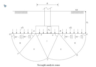
Terzaghi Theory or Terzaghi’s Bearing Capacity Theory

Assumptions

  • Soil is Homogeneous and Isotropic.
  • Soil is fully Saturated.
  • Soil is considered as Hydrodynamic clay.
  • No soil consolidation.
  • Foundation is very Rigid.
  • No applied Moment present.
  • Soil is In-compressible.
  • One dimensional flow.
  • Darcy law is valid.
  • Strain is small.
  • No Sliding occur.

In other words of Terzaghi’s Bearing Capacity Theory

  • 1. Footing base is rough and is laid at a shallow depth (i.e., D f < B).
  • 2. The shear strength of soil above the base of footing is neglected. The soil above the base is replaced by a uniform surface,  g D f .
  • 3. The load on the footing is vertical and uniformly distributed.
  • 4. Footing is long, i.e., L/B ratio is infinite, where B is width and L is the length of the footing.
  • 5. Shear strength of soil is governed by Mohr–Coulomb equation.


Zones: Zone I is elastic zone, zone II is radial shear zone and zone III is passive zone.


Rankine's Theory of Earth Pressure

    Rankine’s theory (1857) considers the state of stress in a soil mass when the condition of plastic equilibrium has been reached.i.e. when shear failure is on the point of occurring throughout the mass.

Assumptions

  • Soil is Homogeneous and Isotropic and 
  • semi-infinite mass of soil with a horizontal surface
  • Consider Back of the wall is Friction-less or smooth.and vertical.
  • in other word having a vertical boundary formed by a smooth wall surface extending to semi-infinite depth.
  • Back-fill is dry and cohesion-less.
  • Critical Shear surface is Plane.
  • Back-plane is vertical and smooth like no friction.
  • Wall is Infinitely Long.
  • No strain condition occur.
  • Failure type sliding failure.
  • Resultant Force is not parallel to Back-fill Surface.
  • When the horizontal stress becomes equal to the passive pressure the soil is said to be inthe passive Rankine state
  • The Mohr circle representing the state of stress at failure in a two-dimensional element
  • The soil element is in state of plastic equilibrium. i.e in the verge of failure.
  •  The theory satisfies the conditions of a lower bound plasticity solution