Irrigation
Civil Engineering
Types of Irrigation
|
Flow Irrigation
|
Lift Irrigation
|
| Perennial Irriagation |
Direct Irrigation |
Inundation Irrigation |
Storage Irrigation |
Combined Storage and Diversion scheme |
(well irrigation) |
| (The water required is supplied to the crop through out the year) |
(diversion scheme) (or) (River canal irrigation) (Water is directly diverted to canal without storing) |
(The irrigation is carried out by deep flooding) |
(storage scheme) (or) (Tank irrigation) (Water is stored in dam (or) reservoir) |
(Water is stored in dam (or) reservoir and then diverted to canal) |
(Subsoil water is lifted to the Surface and conveyed to agricultural fields.) |
All study of Irrigation in Civil Engineering in Exam point of view
Garret's diagram
It gives the graphical method of designing the channel dimensions based on Kennedy's Theory.
The diagram has discharge plotted on the abscissa and the ordinates on the left indicate the slope and on the right water depth in the channel and critical velocity (Vo).
Kennedy's theory
R.G. Kennedy studied a number of sites at Upper Baro Doab System (now in Punjab) for carrying out investigations about the velocity and depth of channels.
According to him, Critical velocity (Vo) is the mean velocity that will just keep the channel free from sitting and scouring and related it to depth.
Modified critical Velocity,
Vo=0.55md0.64
Where, d = depth of the channel (m), m = Critical velocity ratio (V / Vo) (For sand m = 1.1 to 1.2, for finer sand other than standard m = 0.9 to 0.8)
Further, the Critical Velocity ratio (CVR) is the ratio of actual velocity (Va) to critical velocity (Vc) in the channel.
Now If,
CVR > 1 Va > Vc Scouring will occur.
CVR < 1 Va < Vc Silting will occur
CVR = 1 Va = Vc There will be no silting and scouring
For calculating velocity, He used Kutter's formula and Manning's formula.
Kutter formula
- `V=\left[\frac{\frac1N+\left(23+\frac{0.00155}S\right)}{1+\left(23+\frac{0.00155}S\right)\frac N{\sqrt R}}\right]`
where, R = hydraulic radius
S = slope or gradient
Manning Formula
- `V=\frac1NR^\frac2{3}\sqrt S`
Meandering
- A meander is formed when moving water in a stream erodes the outer banks and widens its valley and the inner part of the river has less energy and deposits what it is carrying.
- A wave phenomena.
- A Meandering river is a river that contains many bends throughout its length.
Causes of Meandering
- Extra turbulence generated by the excess of river sediment during floods.
- Size and grade of sediments that make up the river bed.
- Valley slope.
- Bed slope and side slope of the channel.
- Main cause is Extra turbulence generated by the excess of river sediment during floods.
Meander Parameters:
Meander Length (ML) - The tangential distance between the crests or trough of a mender in plan view.
Meander belt width (MB) - Distance between top and bottom portion of successive crests and trough of a member in plan view.
Meander ratio - Ratio of meander belt width to meander length.
Tortuosity or sinuosity - Ratio of archual length (length along the channel) to the direct axial length.
Head Sluices (or Canal Head Regulator):
- A head sluices or canal head regulator (CHR) is provided at the head of the off-taking canal, and serves the following functions:
- It controls the entry of the silt in the canal.
- It regulates the supply of water entering the canal.
- It prevents the river floods from entering the canal.
Silt Ejectors (or Silt extractors):
- These are the devices that extract the silt from the canal water after the silted water has traveled a certain distance in the off-take canal.
- These works are, therefore, constructed on the bed of the canal, and a little distance downstream from the head regulator.
Under-Sluices (or Scouring Sluices):
- The under sluices are the openings that are located on the same side as the off-taking canal and are fully controlled by gates, provided in the weir wall with their crest at a low level.
- Their main functions are:
- It helps in controlling the silt entry into the canal.
- It scours the silt deposited on the river bed above the approach channel.
- It passes the low floods without dropping the shutter of the main weir.
- It preserves a clear and defined river channel approaching the regulator.
Divide Walls:
- Divide wall is a masonry or concrete wall constructed at the right angle to the axis of the weir.
- Its main objective is to form a still and comparatively less turbulent water pocket in front of the canal head regulator so that the suspended silt can be settled down
- which then later be cleaned through the scouring sluices from time to time.
As per Lacey’s formula, the relation between discharge, Q, and the wetted perimeter is given as:
P=4.75√Q
For a rectangular channel, wetted perimeter P is given as:
P = B + 2 × y
Where y is the depth of flow.
If the channel is very wide the P ≈ B (as y ≪ B)
According to Lacey's theory, the following formulae has been given below:
| Velocity of flow, V | V=(Qf2140)1/6
|
| Hydraulic mean depth, R | R=52V2f
|
| Area of the channel section, A | A=QV
|
| Wetted perimeter, P | P=4.75Q−−√
|
| Bed Slope, S | S=f5/33340Q1/6 |
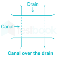
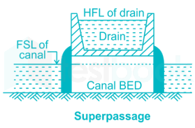
The drainage water intercepting the canal can be classified in the following ways:
i) By passing the canal over the drainage
a) Aqueduct
b) Syphon aqueduct
ii) By passing the canal below the drainage
a) Superpassage
b) Syphon
iii) By the drain through canal ⇒
- a) level crossing
- b) inlets and outlets
Tile drains or under drains
They are located at suitable depths below the ground surface above the impervious soil (clay) which prevent natural percolation of water and usually covered with coarse sand or bajri.
They are preferably placed in a soil of medium or high permeability.
The Tile drains permit deep root development by lowering the water table.
Tile drains have their outlets in natural as well as artificial channels.
Gravitational water at the head of the tile drain is under pressure due to head of water above it.
Drainage coefficient
Drainage coefficient is the rate at which water is removed by a drain.
It is expressed as depth of water in cms or meters to be removed in 24 hours from the drainage area.
It depends on rainfall, type of soil, type of crop, degree of surface drainage etc.
Its recommended value is 1 % of the average annual rainfall to be removed per day.
As per Lacey’s Theory, Normal scour depth is given by :
Case 1: If river width equal to the regime width of 4.75 √Q ; Q is the Discharge
R=C(Qf)13
Where, C is constant, generally taken 0.473.
Q = Design flood discharge and
f = Silt factor and it is given as
f = 1.76 √d; d is particle size in mm
Case 2: For all other values of actual width of river the normal scour depth is given as:
R=c(q2f)13
Where,
C = 1.35 and q is the discharge per unit width.
Further,
Maximum scour depth Smax = K × R
Where, K = 2 (Constant for piers)
It is a phenomenon in which the productivity of land gets affected due to the high water table leading to flooding of the root zone of the plants and making the root zones of the plants ill-aerated.
- Over and intensive irrigation
- Seepage of water from the adjoining lands
- Impervious obstruction
- Inadequate surface drainage
- Inadequate natural drainage
- Heavy rains
- Submergence due to floods High water table
Lift irrigation:
- Irrigation with which water is supplied to the system by water-lifting devices is called pumping/mechanical/lift irrigation (by means of mechanical water-lifting devices).
- It has high operating costs.
- It has fewer problems with waterlogging.
Extensive irrigation:
- These systems are more costly to build and to maintain.
- Irrigation service provided to end-users is often limited to only two to three irrigations per season.
- These systems often have fewer problems with waterlogging and salinity and provide incentives for the conjunctive use of ground and surface water.
Intensive irrigation
- This system uses a large amount of water, labour, and resources for a small area in order to increase production and yield.
- More prone to waterlogging as no limit to the amount of irrigation water.


